|
Pin
No |
Pin Name |
Programmer Input/Output |
Connect to Pin on Target Device |
Description |
|
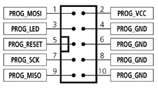
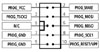
1 |
PROG_MOSI-1
|
O |
MOSI
(Except for ATMEGA103/128/64 - connect to RXD pin instead) |
Master Out Slave in This is the SPI data output pin from the programmer. This pin should be connected to the MOSI pin on the target microcontroller. |
|
2 |
PROG_VCC |
P |
TARGET_VCC |
Target Vcc
This pin should be connected to the Target System Vcc. This voltage could be used to power the programmer depending on the settings of the power switch/jumper on the programmer. |
|
3 |
N/C |
- |
N/C |
Not connected |
|
4 |
PROG_GND |
P |
GROUND |
Ground Connection
Common ground connection between the programmer and Target System. |
|
5 |
PROG_RESET |
O |
RESET |
Target RESET control pin
This pin controls the Target Device RESET pin. It will be driven HIGH/LOW according to the device type and settings in the ‘Pre-program State Machine’ tab in the Eqtools project. |
|
6 |
PROG_GND |
P |
GROUND |
Ground Connection
Common ground connection between the programmer and Target System. |
|
7 |
PROG_SCK1 |
O |
SCK |
SPI Serial Clock Output
This is the SPI clock output signal. |
|
8 |
PROG_GND |
P |
GROUND |
Ground Connection
Common ground connection between the programmer and Target System. |
|
9 |
PROG_MISO |
I |
MISO
(except for ATmega103/128/64 – connect to TXD pin instead) |
Master In Slave Out
This is the SPI data input pin to the programmer. This pin should be connected to the MISO pin on the Target Microcontroller. |
|
10 |
PROG_GND |
P |
GROUND |
Ground Connection
Common ground connection between the programmer and Target System. |