|
|
|
 |
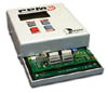
Plugs into PPM3-MK2 Programmer |
|
|
The CALCON Module simply plugs into the PPM3-MK2 Programmer.
|
- Easily removeable from the programmer to allow main programmer board to be swapped without rewiring the Test Fixture
-
Plugs into mating connectors on Equinox programmer.
|
|
What are the connections to the Target System ? |
|
|
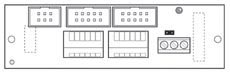
The CALCON Module features the following connectors to connect between the Programmer and the Target Microcontroller:
- 10-way IDC Box Header - Equinox pin-out
- 10-way IDC Box Header - Atmel JTAG-ICE pin-out
- Clip-in wire connectors for JTAG connections
|
|
SPI Connections to Target Microcontroller |
|
|
If you are using the standard SPI interface to program / calibrate the target ATmega microcontroller, the following connections are required between the CALCON Module and Target Chip:
- PROGRAMMER_MOSI / 32kHZ* --> AVR_MOSI
- PROGRAMMER_MISO --> AVR_MISO
- PROGRAMMER_SCK --> AVR_SCK
- PROGRAMMER_RESET --> AVR RESET
*The 32kHz Oscillator is output by the programmer on the PROGRAMMER_MOSI pin during the Calibration Procedure. This pin is used as the normal SPI MOSI Data Out pin at all other times.
|
|
Which pin does the 32kHz clock come out from ? |
|
- The 32kHz oscillator signal is output from the MOSI pin of the programmer to the Target Microcontroller. The Programmer MOSI pin must be TRI-STATED (set to 'TRI') in the 'Pre-programming State Machine' of the project so that it does not try to drive the MOSI pin as well.
|
|
How is the 32kHz clock enabled ? |
|
- The 32kHz clock signal is enabled by asserting Output5 (OP5) HIGH in the 'Pre-programming State Machine' setup of the Programming Project.
|
|
Is the EQ-CALCON Module compatible with the Atmel AVR Oscillator Calibration Firmware ? |
|
|
The EQ-CALCON Module simply provides a 32kHz oscillator under programmer control. The Oscillator Calibration firmware detailed in the Atmel Application Note AVR053 requires to be modified so that the exit condition when executing the Calibration Code is to assert the MISO pin HIGH or LOW.
|
|
Calibration Procedure |
|
|
The Calibration Procedure involves programming custom 'Calibration Firmware' into the Target AVR Microcontroller and then allowing this code to execute while the 32kHz oscillator is fed into the MOSI pin. The firmware writes the Calibration Coefficient(s) into the Target Device EEPROM area and asserts the MISO pin back to the programmer to tell the programmer that is has performed the calibration calculations. The programmer then stops execution of the 'Calibration Firmware' and reads back the Calibration Coefficient(s) from the Target Device. It is then possible to program these Calibration Coefficient(s) back into the Target Device FLASH or EEPROM area or to pass them to another application for further processing using a field in the Equinox Interface Database.
The sequence of events for the 'Calibration Procedure' is as follows:
- Programmer programs 'Calibration Firmware' into the Target Device
- Programmer switches on 32kHz Clock Signal to the MOSI pin of the Target Device
- Programmer releases the RESET pin allowing the Target Device to execute code
- Target Device executes Calibration Firmware
- Calibration Firmware writes the 'Calibration Coefficient(s)' into the Target Device EEPROM
- Calibration Firmware asserts the MISO pin eg. HIGH
- Programmer detects Calibration Firmware has finished and asserts the RESET of the Target Device so it stops executing code and also switches the 32kHz oscillator OFF
- Programmer reads the 'Calibration Coefficients' from the Target Device EEPROM
- Programmer programs the 'Production Firmware' into the Target Device
- Programmer programs the 'Calibration Coefficients' back into the desired location of FLASH or EEPROM in the Target Device
|
|
Does the Calibration Module work in Programmer Standalone Mode ? |
|
|
Yes, as long as the target AVR Microcontroller features the 'EESAVE' fuse....
The Atmel 'Calibration Firmware' writes 'Calibration Coefficient(s)' into the EEPROM area of the target AVR microcontroller during the calibration procedure. In order to preserve these coefficients when the target device is erased and re-programmed, it i necessary to enable the 'EESAVE' fuse in the target device. Once enabled, the AVR can be erased and the firmware can be re-programmed with the final 'Production Firmware' without erasing the EEPROM area. This means that a set of 'chained' Standalone Programming Project can be used for the entire Oscillator Calibration Procedure.
If the target AVR microcontroller does not feature the 'EESAVE' fuse.....
If the target AVR device does not have an 'EESAVE' fuse then there is no way of retaining the Calibration Coefficients in the AVR EEPROM when the device is erased. This means that the programmer can program the 'Calibration Firmware' and run the 'Calibration Firmware' in Standalone Mode, but it must be controlled via a 'Programming Script' running within the Equinox ISP-PRO software in order to read the Calibration Coefficient(s) from the Target Device EEPROM and also to write these coefficient(s) back into the Target Device.
|
|
What hardware / software is required for on-board Oscillator Calibration ? |
|
|
The following hardware / software components are required to implement the on-board calibration of the Internal Oscillator of an Atmel AVR microcontroller:
Hardware:
- PPM3-MK2 Programmer
- EQ-CALCON - Oscillator Calibration Module
Software:
- EQTools - Programmer Configuration Software
- ISP-PRO - required for running Programming Script(s)
|
| |