|
# |
Connector Name |
Description/Comment |
|
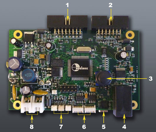
1 |
Target ISP Connection Port |
● This Port features all the Target I/O Signals."
● 5 x Programmer controlled I/O lines
Multiplexed for SPI, JTAG, UART, BDM, PDI
● 1 x Programmer Output line (e.g. Relay control)
● Dedicated 2-wire I2C Port
● Controlled Target Vcc Supply |
|
2 |
Programmer Remote Control Port |
● This port is used to control the programmer from e.g. an ATE via a “4-wire TTL Interface”.
● The “Remote Status LEDs” PASS, BUSY, FAIL are also on this port. This allows LEDs to mounted on the lid of the Test Fixture for easier visibility. |
|
3 |
START Button |
● Executes a “Standalone Programming Project” |
|
4 |
RS232 Port (2) or Remote Display Keypad |
RS232 Port (2) - Serial Communications Port
● This port can be used to control the programmer via an RS232 link from a PC or other Test Equipment.
● A ‘Remote Display / Keypad Module’ can also be connected to this port allowing the programmer to be remote controlled.
● The connector is a 4-pin RJ11 connector |
|
5 |
USB Port |
USB Port
● This port can be used to control the programmer via a USB link from a PC or other Test Equipment. |
|
6 |
RS485 Ports |
RS485 Ports (1) + (2) - Serial Communications Ports
● These port can be used to control the programmer via an RS485 link from a PC. They are connected in parallel internally so it does not matter which is used as the RS485 INPUT or OUTPUT.
● The connector is a 5-pin 2.54mm Molex. |
|
7 |
Programmer STATUS LEDs |
Programmer ‘Status’ LEDs
From Left to right:
● PASS (GREEN)
● BUSY (YELLOW)
● FAIL (RED) |
|
8 |
EXTERNAL TARGET VCC INPUT |
EXTERNAL TARGET VCC INPUT
● DC Power Input to power the programmer
● Voltage range: 3.0 – 24.0 V DC (right-hand pin positive) |
|
9 |
DC Power Input |
DC Power Input to power the programmer
● Voltage range: 9.0 – 24.0 V DC (right-hand pin positive) |