| |
Frequently Asked Questions (FAQ): |
|
|
|
|
|
|
 |
Advantages |
|
- Supports In-System Debugging (ISD) via suitable external debugger e.g. Atmel JTAG-ICE
-
Supports high-speed In-System Programming (ISP) via the JTAG port of the Target Microcontroller
-
The same JTAG port can be be used for both ISP and Debugging
|
|
AVR JTAG - Further information |
|
|

For further information about the 'AVR JTAG' programming method, please CLICK HERE
|
|
Equinox portable / field programmers supporting AVR JTAG: |
|
|
The following Equinox portable / field programmers support the Atmel 'AVR JTAG' programming interface:

Click the programmer picture for more information about the selected programmer.
|
|
Equinox production programmers supporting AVR JTAG: |
|
|
This 'Device Library' is compatible with any of the Equinox programmers listed below:

Important notes:
- The ISPnano Series 3, Series S3 ATE, Series 4 ATE and GANG programmers require a 'Device Library' per programmer channel.
- The ISPnano-MUX programming systems only require one licnese per programmer.
|
|
Atmel Tools Compatability |
|
- Atmel JTAG-ICE (Equinox programmers use the same pin-out as this ICE)
-
Atmel STK501 AVR FLASH Microcontroller Starter Kit
-
Atmel STK502 AVR FLASH Microcontroller Starter Kit
|
|
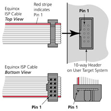
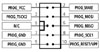
ISP Header Pin-out |
|
|
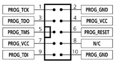
The table below details the pin-out connections of this header
|
Pin
No |
Pin Name |
Programmer Input/Output |
Connect to Pin on Target Device |
Description |
|
1 |
PROG_TCK
|
O |
TCK |
JTAG TCK – Test Clock Signal pin
Clock signal from programmer to Target Device JTAG port |
|
2 |
PROG_GND |
P |
GROUND |
Ground Connection
Common ground connection between Programmer and Target System |
|
3 |
PROG_TDO |
I |
TDO |
JTAG TDO – Test Data Output pin
Data signal from Target device JTAG port to programmer |
|
4 |
PROG_VCC |
P |
TARGET_VCC |
Target Vcc Connection
- Pins 4 + 7 are physically connected inside the programmer.
- Connects to Vcc rail of Target System.
- Pin referred to as VTref on Atmel JTAG-ICE |
|
5 |
PROG_TMS |
O |
TMS |
JTAG TMS – Test Mode Select pin
Mode Select Signal from programmer to Target Device JTAG port |
|
6 |
PROG_RESET |
O |
RESET |
Microcontroller RESET control signal
This pin connects to the main RESET pin of the Target Microcontroller. This pin is not strictly needed for JTAG programming, but it can be used to RESET the Target Device before and after programming |
|
7 |
PROG_VCC |
P |
TARGET_VCC |
Target Vcc Connection
- See pin 4
- Pins 4 + 7 are physically connected inside the programmer |
|
8 |
N/C |
O |
N/C |
Not Connected |
|
9 |
PROG_TDI |
O |
TDI |
JTAG TDI – Test Data Input pin
Data signal from programmer to Target Device JTAG port |
|
10 |
PROG_GND |
P |
GROUND |
Ground Connection
Common ground connection between the programmer and Target System |
Key
O - Output from programmer to Target Device
I - Input to programmer from Target Device
P - Passive eg. GROUND and power rails
N/C - Not connected
|
| |